Static VAR generator (SVG) is a representative of the latest technology in the field of VAR compensation. SVG in parallel in the power grid, equivalent to a variable reactive current source, the reactive current can be flexibly controlled, automatic compensation system required reactive power. Because of its extremely fast response speed, it is also called Static Synchronous Compensator (Static Synchronous Compensator). STATCOM).
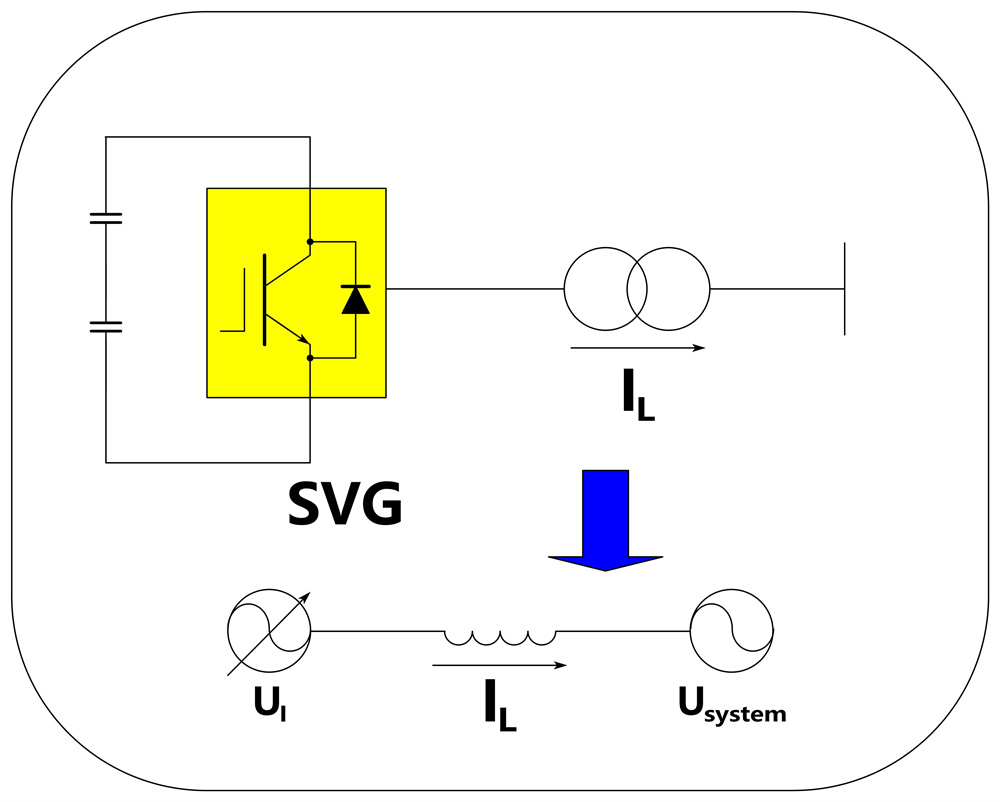
The technical basis of SVG is Voltage Sourced Converter. The basic principle is to use high-power power electronic devices such as IGBT that can be turned off to form a self-commutating bridge circuit. The DC voltage is converted into AC, and then connected to the grid through the reactor, and the amplitude and phase of the output voltage on the AC side of the bridge circuit are adjusted appropriately. Or directly control its AC side current can make the circuit absorb or emit reactive current to meet the requirements, to achieve the purpose of dynamic reactive power compensation.
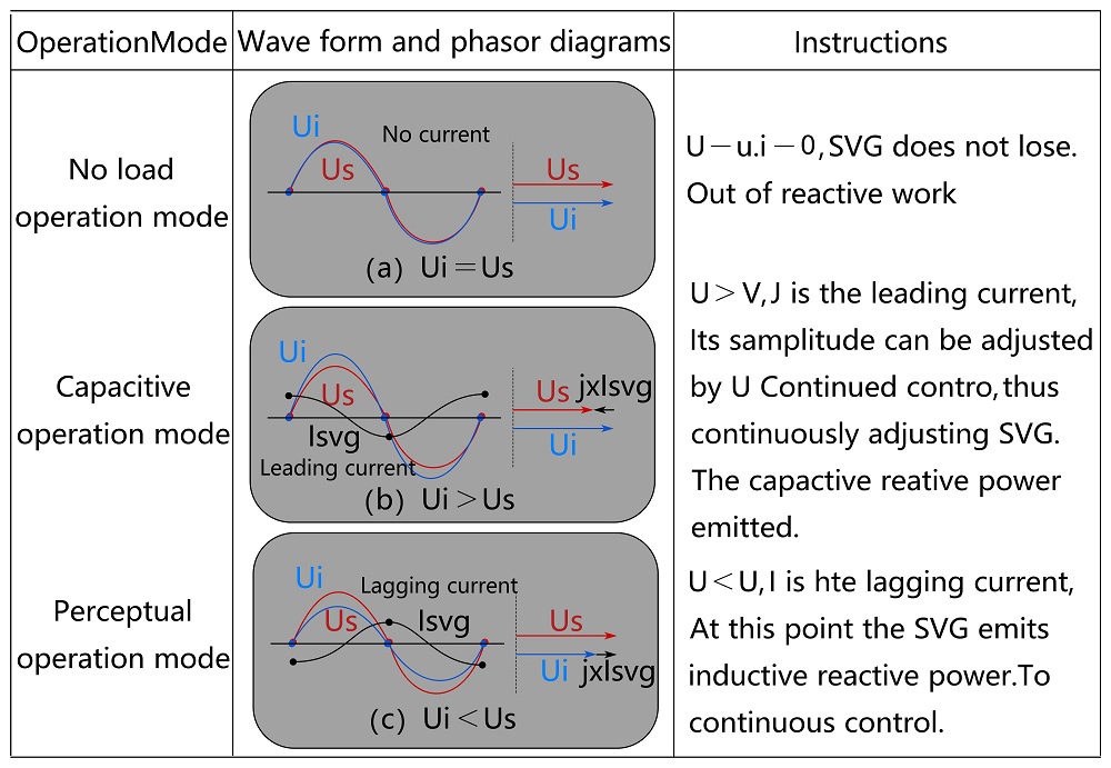
Type explanation

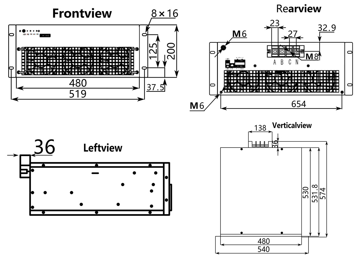
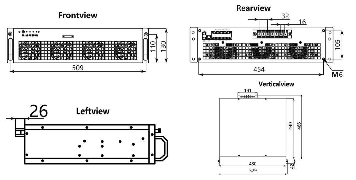
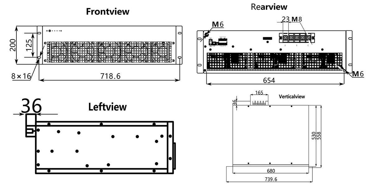
Product dimensions
380V 150kvar module
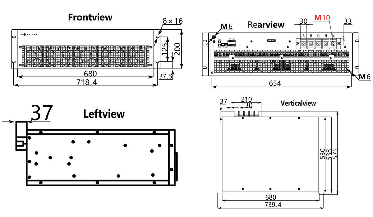
380V 100kvar Modules
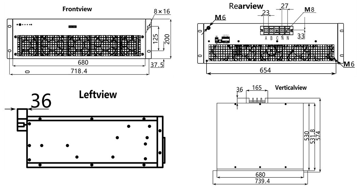
380V 50kvar module
380V 30kvar module
660V 100kvar/50kvar module
● Modular design, any module failure will not affect the normal work of other modules, greatly improve the reliability of the whole equipment; It can realize smooth expansion of multiple units running directly in parallel. When multiple devices are added, the master/slave control mode is adopted. When multiple modules are connected in parallel, all modules can share a set of current transformer;
● Reactive compensation can bring the power factor up to 1
● Adopts the fifth-generation IGBT of international famous brand, which can automatically adjust the output according to the reactive current of the load and dynamically compensate.
● Adopt military FPGA control chip, fast running speed, high reliability;layered design, dust and rain will not be attached to the circuit board, adapt to the use of harsh conditions;
● Using the sliding window iterative DFT detection algorithm, the calculation speed is fast, the instantaneous response time is less than 0.1ms, and the compensation full response time is less than 20ms.
● Has a complete protection function, including overvoltage, overcurrent, overheating, short circuit and other complete protection functions, and has the system self-diagnosis function;
● Adopt reliable current limiting control link, when the system to be compensated current is greater than the rated capacity of the device, the device can automatically limit the current at 100% capacity output, maintain normal operation, will not appear overload and burn and other failures;
● To save space for the user, the maximum power of the 600mm wide cabinet is 400kvar, and the power of the 800mm wide cabinet is up to800kvar.
Category | Item | Index | ||||||
| Voltage level | 380V | 660V | |||||
Module specification | 30kvar | 50kvar | 100kvar | 150kvar | 50kvar | 100kvar | ||
(W*H*D) | 480*130*440 | ✔ | ||||||
480*200*530 | ✔ | |||||||
680*200*530 | ✔ | |||||||
680*200*550 | ✔ | ✔ | ✔ | |||||
Shunt quantity | 12 | |||||||
| Working Voltage | 380V(-10%~+10%)、660V(-10%~+10%) | ||||||
Operating frequency | 50Hz(-10% ~ +10%) | |||||||
|
| 2-13 times (50% of rated current)current-rated | ||||||
Compensated reactive power | -1 to +1 Adjustable (device capacity range) Adjustable (equipment capacity range) | |||||||
Compensation for three-phase unbalance | 100% unbalance fully compensated | |||||||
communication agreement | Communication mode | RS485 and Modbus protocols | ||||||
Communication Interface | RS485 | |||||||
upper computer software | Yes, all parameters can be set by the host computer | |||||||
Fault alarm | Yes, it can record up to 500 alarm messages | |||||||
Monitoring | Supports independent monitoring of each module or centralized monitoring of the entire system | |||||||
Technology
| Full response time | ≤20ms | ||||||
Active power loss | ≤2.5% | |||||||
Heat dissipation mode | Intelligent air cooling | |||||||
Noice | ≤60dB | |||||||
Protection function | Over voltage, under voltage, overheating, overcurrent, short circuit and other more than 20 kinds of protection | |||||||
CT installation position | Load side/Power grid side Optional | |||||||
| Operating temperature | -10℃~+50℃ | ||||||
Altitude | <5000 m (over 1000 m, the capacity is reduced by 1% for each additional 100 m) | |||||||
Relative humidity | <95%, no condensation | |||||||
Pollution resistance class | Module IP20+ electronic layer IP42 (customizable IP54) | |||||||
Pollution resistance class | Level 2 (Variable Pollution resistance class system Level 3) | |||||||